2 part form, 15 ply seat.

At this point in the bent plywood chair everything had been formed except for the seat. All of the other laminations had been done with cauls and clamps so I decided to forgo digging out the vacuum bag and clamp the seat panel as well. Pressed using 15 ply's of alternating grain maple veneer.


plywoodchair.jpg
plywoodforming.jpg

Time to strap

With the back legs / armrest and back of the chair pressed on the large original form it was time to sort out how to go about pressing the front legs. Faced with the same dilemma of trying to wrap veneer around the diameter of a pencil I looked for alternative ways to clamp around the curve from my original bends. The solution I came to was using a shim steel strap to create my clamping pressure around the outside of the tight radii. 

laminating.jpg
strap.jpg
straplaminating.jpg

So as you can see above the shim steel strap is attached to my plywood clamping cauls. It wraps around the far end of the bordering cauls and into a bandsaw kerf which is then covered with a block to keep the strap from slipping.  

The 21 layers of veneer were cut to shape, the inside three layers were hot pipe bent around the bar of an F-clamp to prebend the tightest radii. 

veneerbending.jpg
bentveneer.jpg
laminating.jpg
woodbending.jpg
woodform.jpg

So you can see in the pictures above the two clamps that are clamping down the length of the cauls on either side of the bend, these are tightened at the beginning of the glue up to pull the strap tight around the corners where the blocks don't cover the lamination.

bentwood.jpg
woodbending.jpg

Like most chairs it required a set of lefts and rights, so two forms with complimentary angles were needed. They turned out better than expected and I was amazed at how well the strap technique worked. On to the seat and then lots of clean up and shaping. 


It Lives

It's been close to year since I had to admit defeat with the Origami Chair. The time I had available to work on it had run out and there was a long list of previously designed commissioned work with fast approaching deadlines. 

I am fortunate to have very understanding clients and Jed is no exception. So, after a long delay, we are back Origami Chair, and we have come to snatch victory from the jaws of defeat. 

That big form from last year did get used. We did attempt to press the back legs, back rest and arm rest as one complete panel, it didn't work. Maybe it was the expansion / contraction from the moisture in my glue with alternating grain, maybe it was a lack of pressure in certain parts of my form, the point of the matter is it failed. Love your experiments, calm your brain, move forward. 

Once back at the drawing board the decision was made to forgo the idea of a chair composed of just 2 panels (parts). A little bit of an adjustment to the original form and I was able to press the back legs, and arm rests separate from the larger back panel. Basically I would create what you see above in three pieces instead of just one. 

These are the parts I managed to make last year before having to move on. There was still a glimmer of hope that this could all work out. What came next was maybe the biggest personal wood bending breakthrough I have experienced. Laminating with a strap. 


Valet Chair

At the end of 2014 we finished up a commission for a custom valet chair. The customer was fond of our aesthetic and wanted to see what our take on Hans Wagner's iconic Valet Chair (1954) would be.

Hans Wagner - Valet Chair (1953)

Hans Wagner - Valet Chair (1953)

As par the standard commissioning process we created 3 concepts for the client, what's below is the one he wanted to see become a reality. For those not familiar, the valet chair is intended to be a chair that accommodates getting dressed / undressed. The back of the chair (like many chairs) is to hang a suit jacket/blazer. What's unique from many chairs is the "clothes hanger" section is shaped to replicate ones shoulders, (higher end jackets often have horse hair pads in the shoulders, the shape of the shoulders helps to keep the shape of the jacket). This was the only real criteria from the client, he even provided a hanger to reference. 

The seat on the chair hinges from the front edge providing a place to fold / hang trousers over as well as exposing a leather lined compartment for ties / belts / cuff links / wallet / phone / keys and anything else you may want to store. 

This valet chair forced me to evaluate a different set of requirements within a familiar form. Yes, like all chairs this one needed to be strong, and have an appealing aesthetic. Where it differed is the emphasis on this chair was not in comfort (it did turn out very comfortable by coincidence), but instead in creating a chair that one could easily and intuitively get dressed / undressed using day in and day out. 

Below are the original two valet chairs created in walnut, with leather details and custom fabricated brass hinges. 

valetchair
valetchairfront
suitchair
bridle


You call that a form?

It has been quite the journey since proving the folded paper concept could work. I have gone through many, many sheets of particle board / mdf and more coffee than I care to admit. It has taken days to build, and days to refine and alter. This form could likely keep the building from flying away in case of a hurricane at this point. I am not entirely sure how I managed to sort it all out, but somewhere amongst the caffeine and sleepless nights  (possibly related) I sorted through the angles, and the angles where angles meet angles.

The form is composed of 6 separate torsion boxes. Together they give me the angles I require, or at least I certainly hope so.

With the form "complete" I needed to devise a clamping strategy (no way this contraption was fitting in the vacuum bag). A clamping caul system was the only way I could conceive making it work, and so the adventure of making an elaborate set of clamping cauls began. 1.5" thick mdf formed the platens (compound angles meeting compound angles) that would sandwich the veneer with "sprung" beams running across them. Because I won't be able to get a clamp into the center of the panel and I don't own any 12" deep clamps I needed to "spring" the beams. Basically the beams are touching in the middle (peak of the triangle profile) of the platen and around an 1/8" high on each end where the clamping pressure will be applied. As the clamps get tightened they will close that 1/8" gap creating more pressure in the middle of the platen. Simple stuff really.

This is the first of two forms that will be used to make the chair. This one will be used to create a bent ply panel that will form the back rest, arm rests and back legs.


IMG_6707_opt IMG_6719_opt IMG_6728_opt IMG_6730_opt IMG_6741_opt IMG_6746_opt IMG_6750_opt IMG_6752_opt IMG_6758_opt IMG_6774_opt IMG_6779_opt


Origami Chair

This past autumn I was commissioned to build a chair by a student in the Chair Design class I was co-teaching with Jeff Miller at the Center for Furniture Craftsmanship. During the brainstorming / model making / getting creative energy flowing exercise the student (Jed) came up with a captivating model by "simply" folding paper together into the form of a chair. 
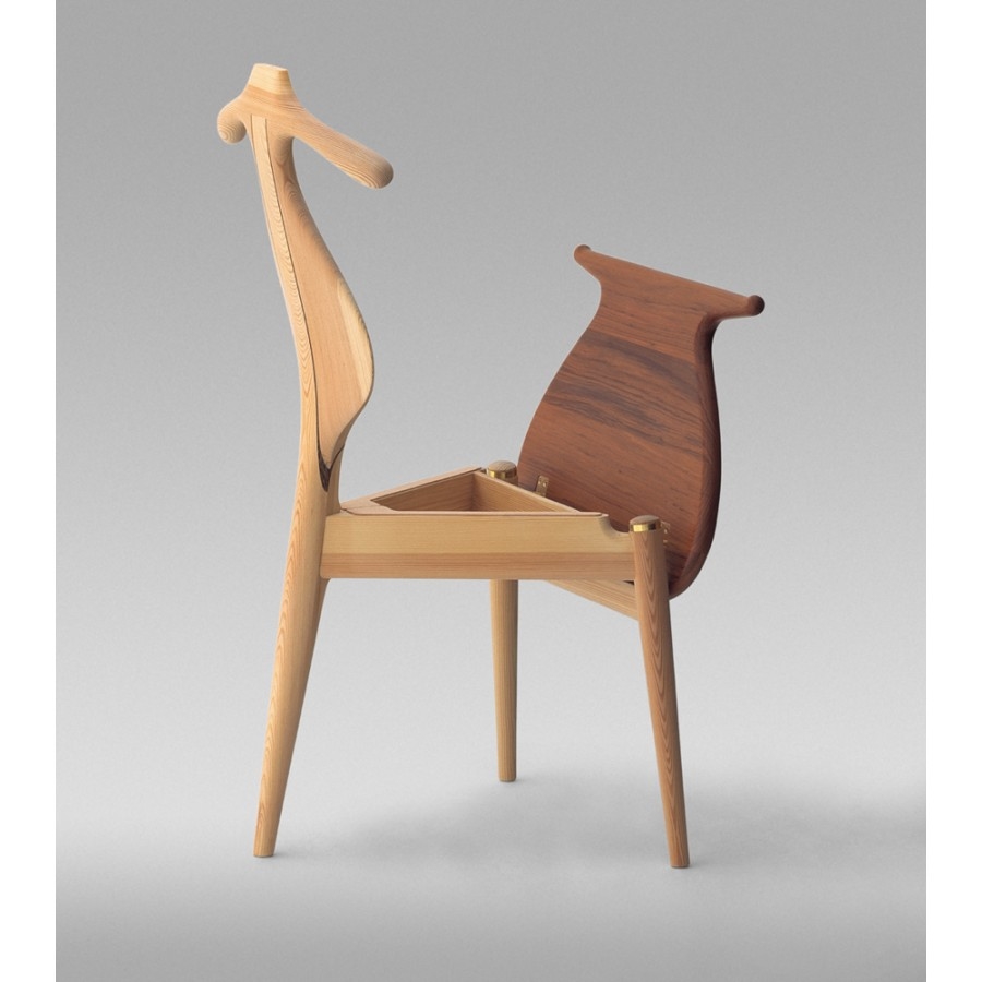
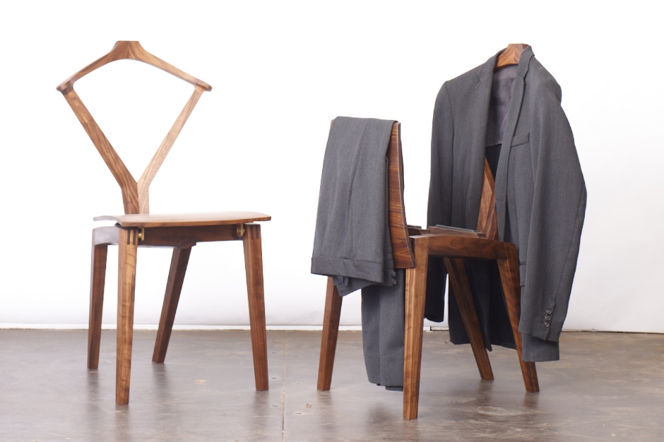
I wish I had decent pictures of the model, but let me tell you, Jeff and I were both immediately drawn to this concept and the potential it had. After a day or two of head scratching our collective brain power was getting pretty mushy, Jed's chair was redesigned capturing some of the elegant lines the model had into a design Jeff, Jed and I were confident in Jed being able to build in just over a weeks time. By the end of the class Jed had created a striking, sit able chair, but he longed to see that original folded together model come to life. Jed commissioned me to make the original design, the endeavour took on a new life.

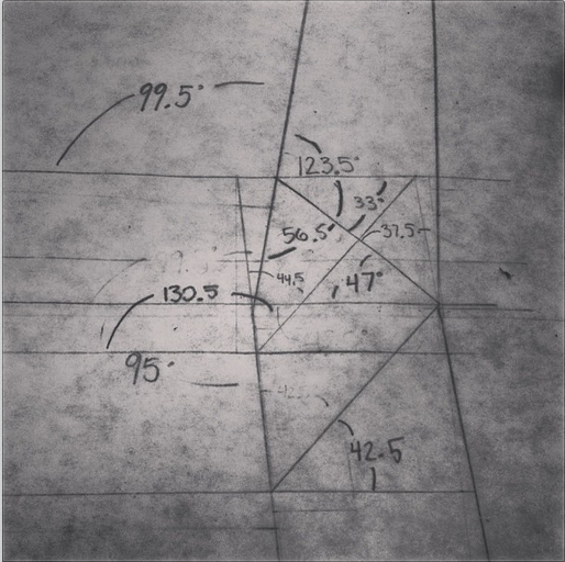
I knew I had gotten myself into a pretty hefty challenge, but let me tell you, I greatly underestimated what lay ahead. Fold some veneer here, fold some veneer there, voila, chair. I knew it was going to be labour intensive, but what I did not anticipate was the mathematician level of trigonometry / master origami problem that lay before me.

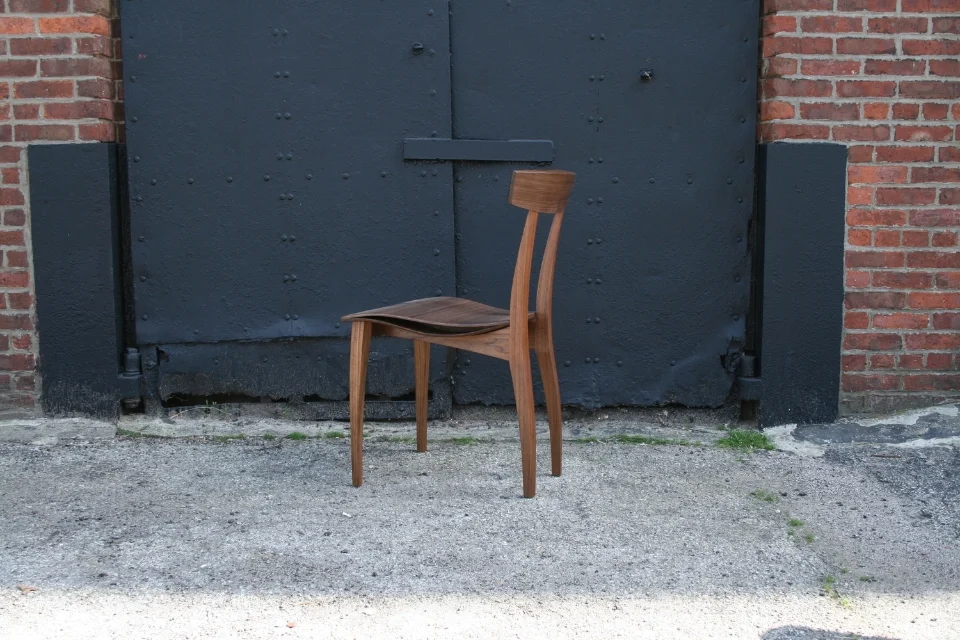
I started in my sketchbook (like always) and came up with a few reiterations of the chair I was content with and started trying to decipher just how to build one of them. After more head scratching I realized I was chasing the wrong concept altogether, and that in reality I wasn't pleased with any of the three concepts I was initially working on. I was trying to merge Jed's original model, his finished redesigned chair and something I thought would be comfortable into a pretty little package. I had ended up in a place with a chair that lacked a cohesive look and feel, I reached out to Jed wanting to discuss the project with him. Jed had no interest in seeing and adding input on the designs, he wanted me to find the right design for myself, to look past the hangups and let my voice be heard. It was a deflating and empowering moment all at once. I took a long walk, enjoyed some fresh air, and realized I needed to go back to the start. I got out the paper, and for what seemed like days folded together both model sized and full sized chairs. From here my current concept was born. I ended up straying a bit from the original model Jed had folded together back in September, but have found a direction I believe will lead to a very unified, refined looking piece.

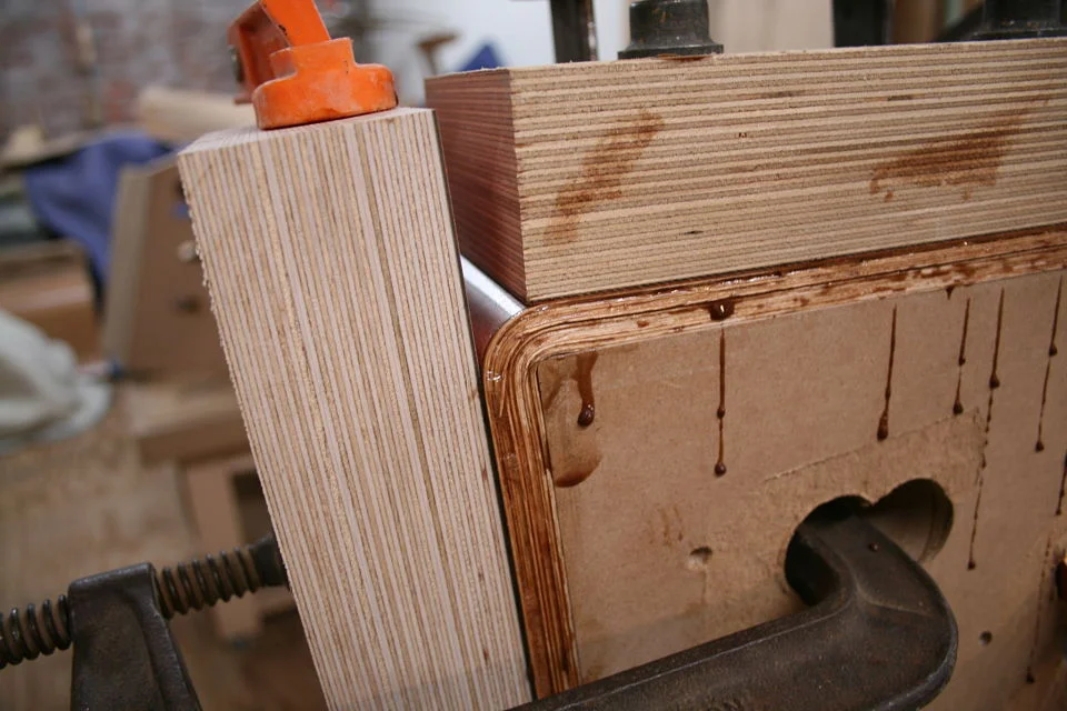
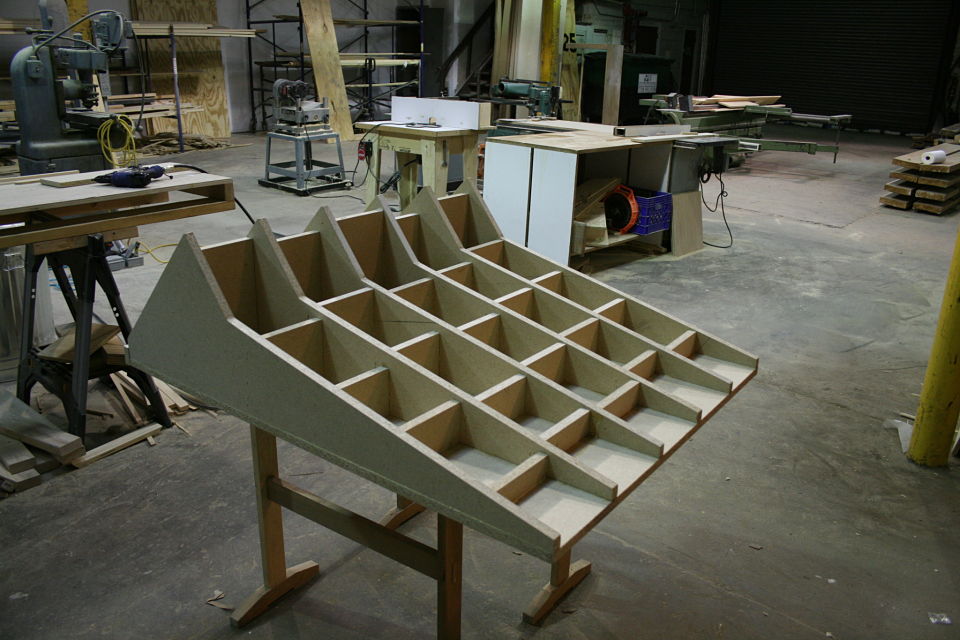
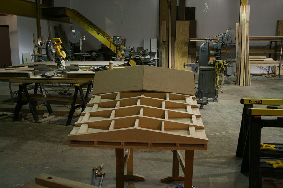
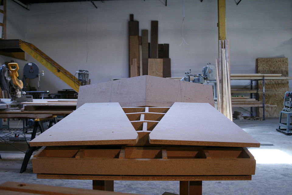
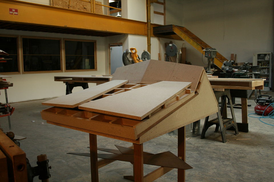
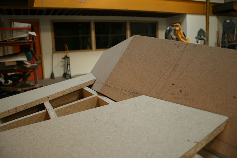
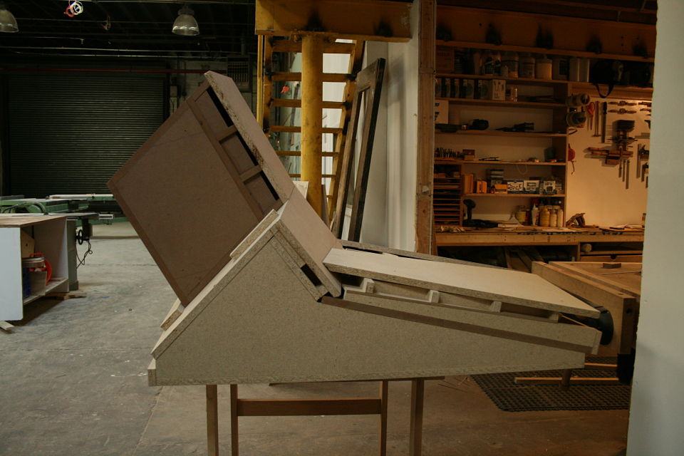
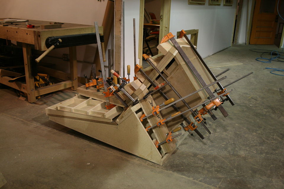
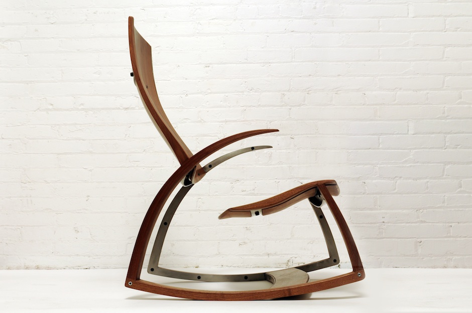
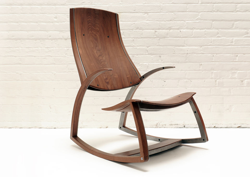
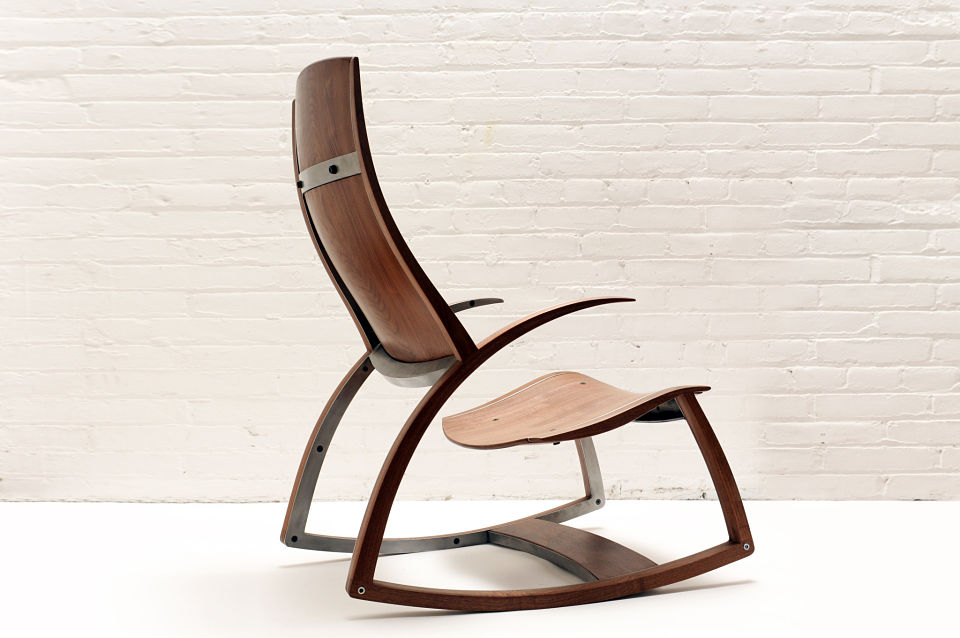
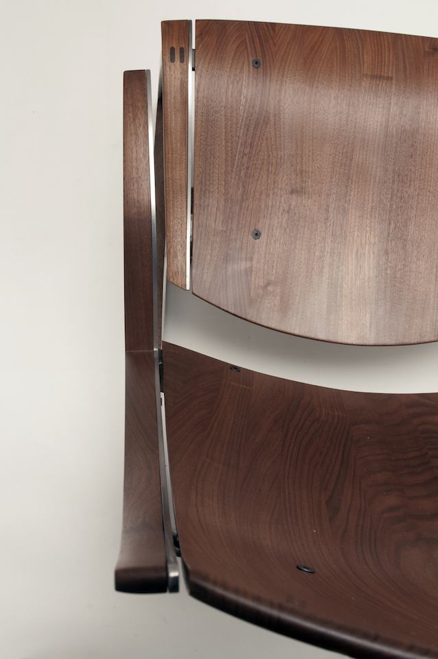
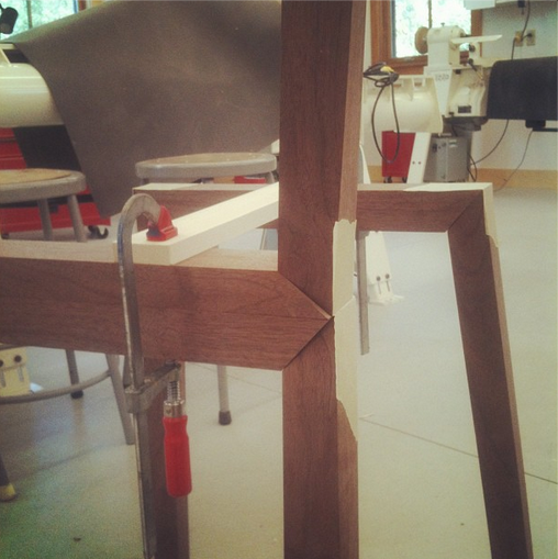
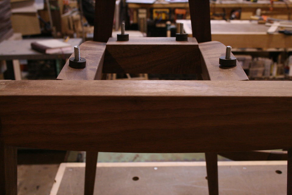
The plan is to make the chair out of just two parts, seems easy enough right? The first part will be a bent panel that makes up the back rest, arm rests, and back legs of the chair. The second part will be a bent panel that makes up the front legs, seat, and another set of back legs. The two panels will then be joined (glued and bolted) up the back leg. Both panels will be pressed out of commercial veneer with alternating grain direction to essential be shop made plywood, this way it will be strong and stable. There will be relief cuts in the veneer to allow for the panels to split apart (top of the back rest and front of the seat) where the panels change the plane they are being bent on.

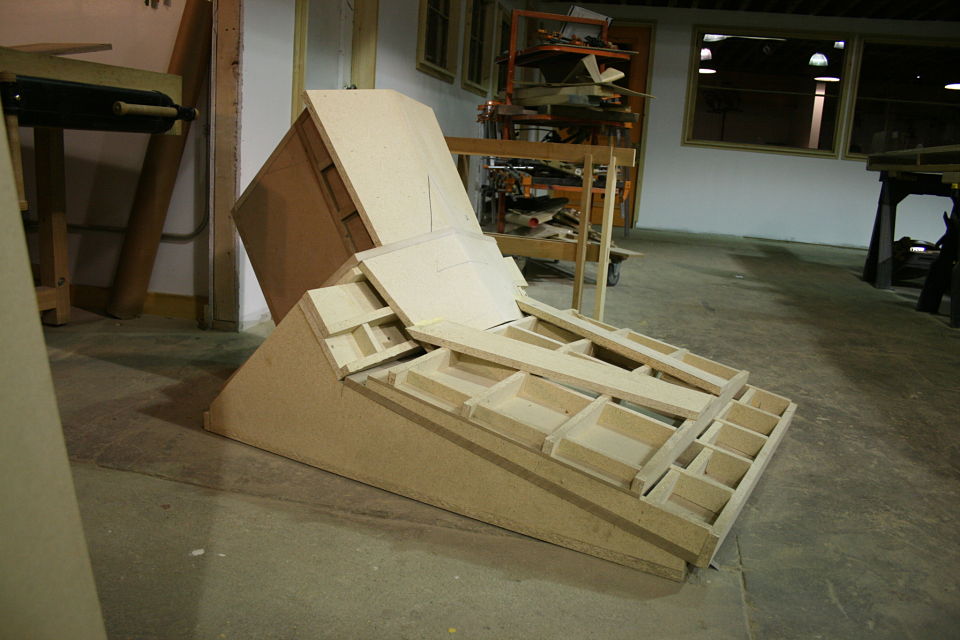
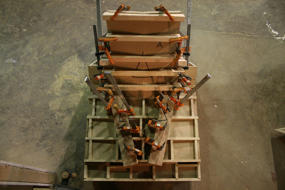
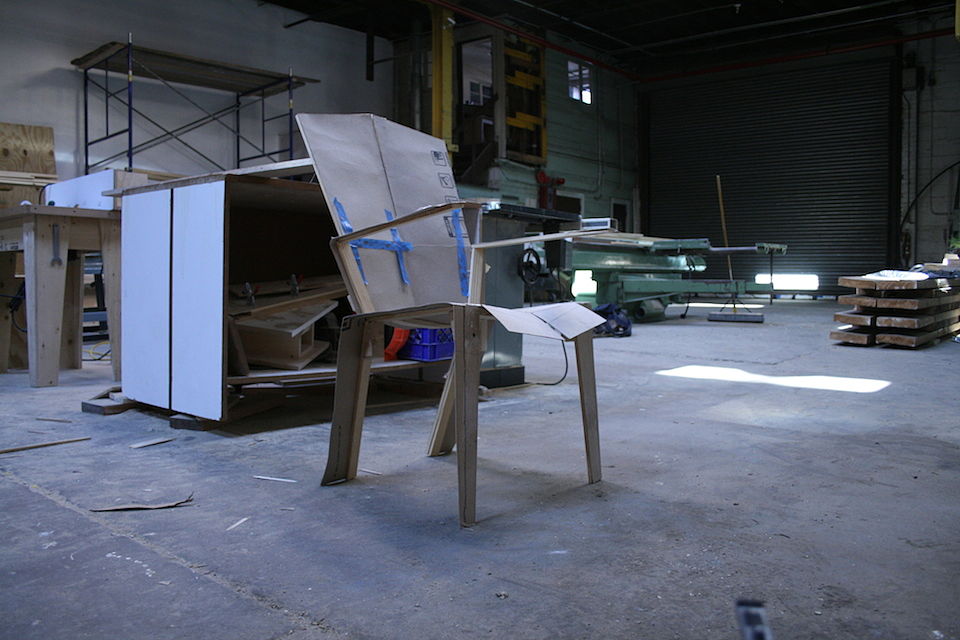
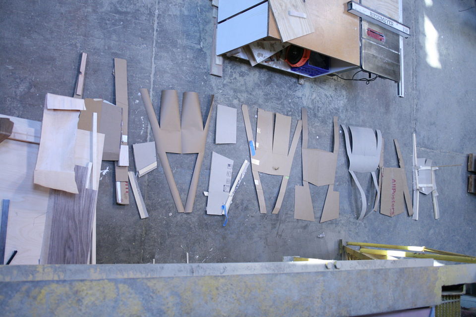
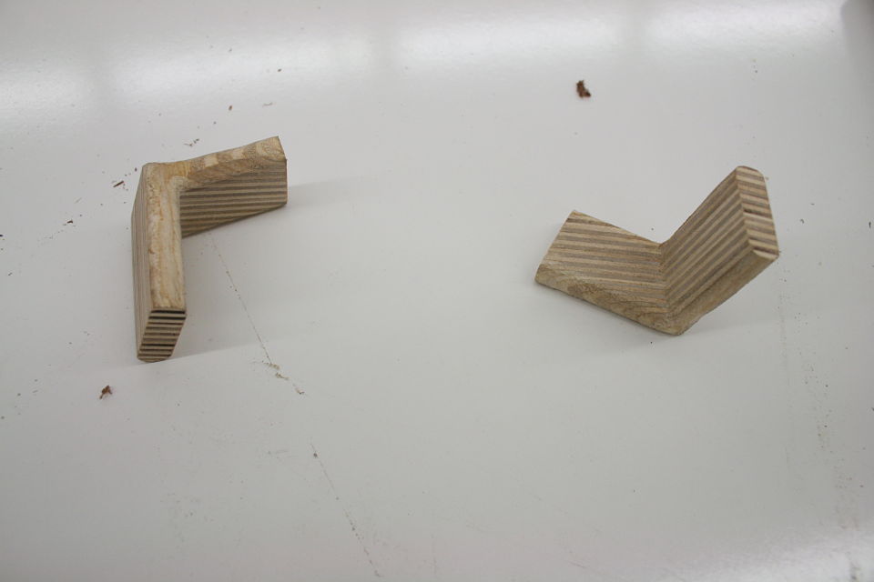
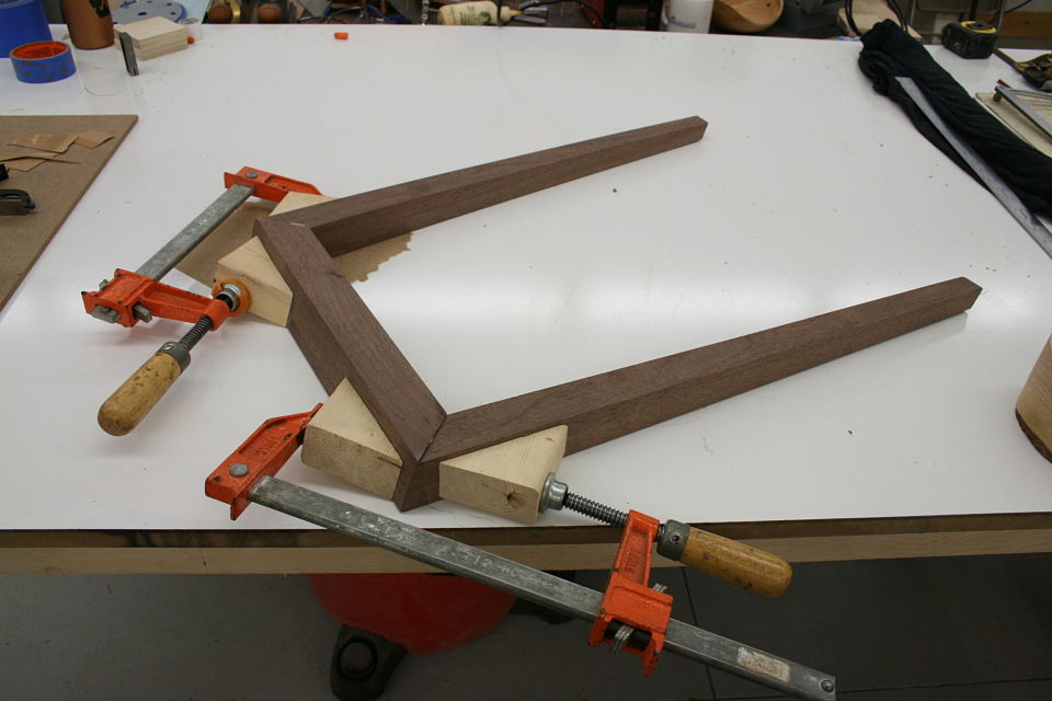
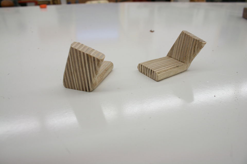
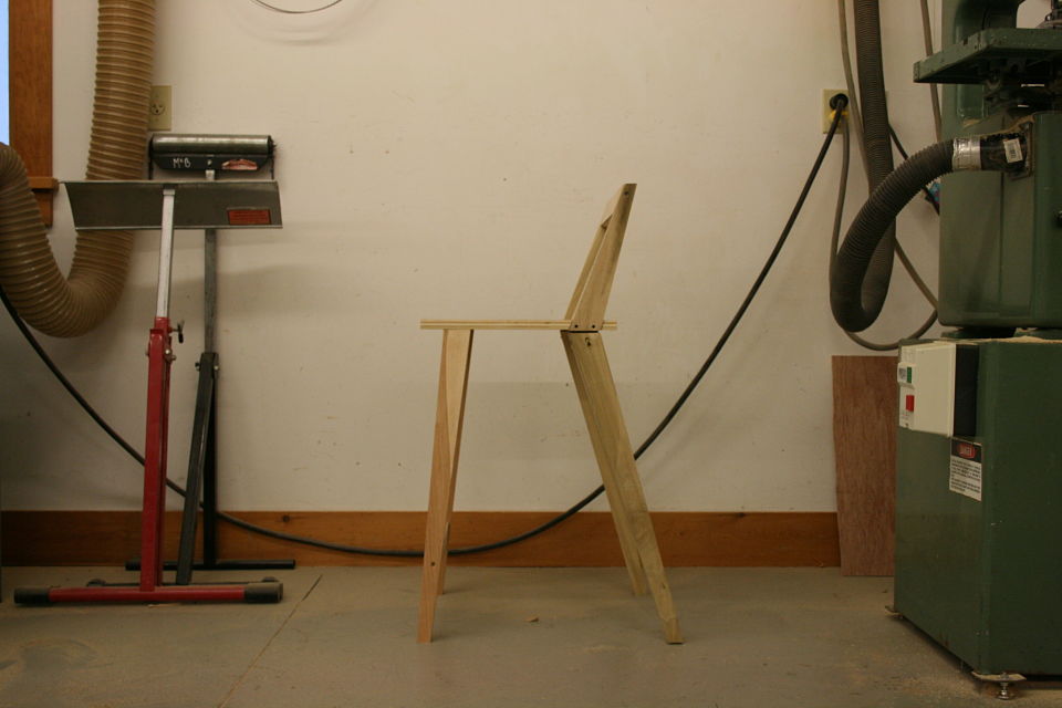
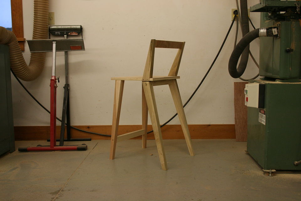
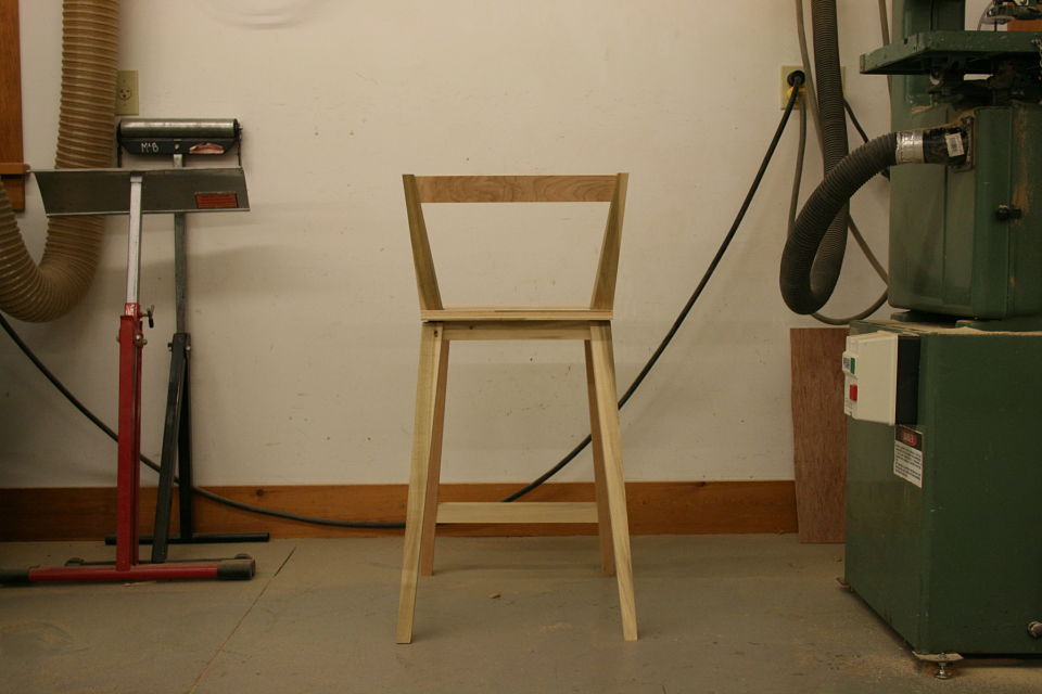
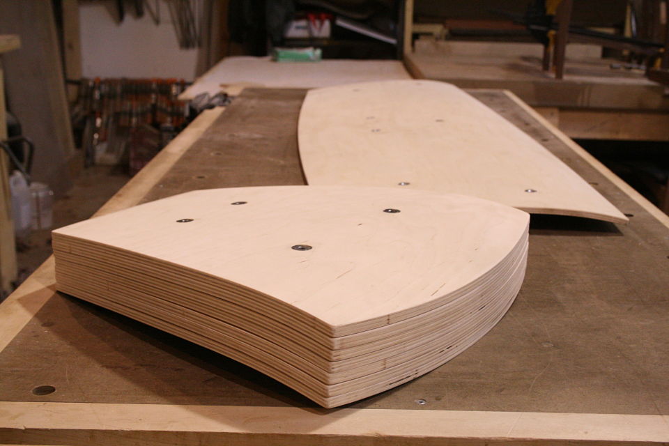
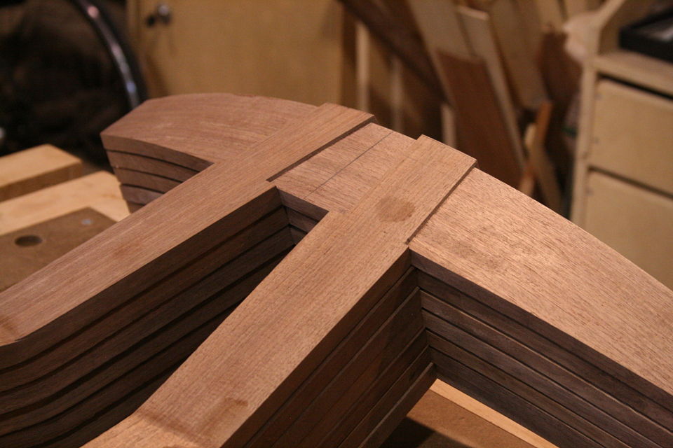
Pictured below are a few (of what seems like hundreds at this point) of my mockups. They are cut from paper, cardboard, and one version made out of plywood to get something rigid enough to take angles from and sit in to work through ergonomics.

I know it doesn't seem like much yet, but stay tuned, this will be a learning intensive journey for everyone involved.

IMG_6636
IMG_6636
IMG_6666_opt
IMG_6666_opt
IMG_6676_opt

IMG_6676_opt

IMG_6696_opt
IMG_6696_opt

Rocking Chair Debuts at the Interior Design Show

Azure-Emerging-Reed-Hansuld-2I know it has been a long time between posts, the business and life side of all this took priority for a little while. Through January and February I was preparing for and exhibiting at the Toronto Interior Design show as well as relocating to Brooklyn, New York. In this post is a picture from the show as well as the most recent piece produced, Rocking Chair No. 1.  It is walnut construction with a steel subframe, the steel gives the piece the structure it requires to take the load of a person. The cool (and somewhat unexpected) thing about it is the chair has no noticeable flex from the cantilevered seat or back, but has a slight flex side to side. It allows the back and seat to move independently from one another as the sitter adjusts in the chair.

I will go back in the coming weeks to post the process of creating this chair as well as posting about a new chair commission I am in the midst of currently designing.

Thanks for following, hope you enjoy.

DSC_6824-editSmaller DSC_6863-Edit_opt DSC_6912-edit_optDSC_6952editSmaller


Bar Stool Prototype

IMG_6582_opt Recently finished up the walnut prototype of the counter height bar stool I began designing while co-teaching the chair design workshop with Jeff Miller at the Center for Furniture Craftsmanship this past October. The minimal structure and clean kinked lines was inspired by a students chair design. The miters joining up in the back of the stool to give the "birdsmouth" look came about as a bit of an accident, a pretty happy accident perhaps going back to my days sharing studio space with Brian Reid.

Already there are some changes I think I would make in the next reiteration. For one I think I would like to pull the foot of the back leg in a some, the stance is a little too extreme for my taste. A wise chair maker once told me, "every chair you ever build is a prototype, you will always see improvements you can make no matter how many of them you have made." With that said I would like to welcome the counter height bar stool no. 3 to the family and look forward to testing this one out and developing it as time goes on.

IMG_6562_opt IMG_6569_opt


The Indestructible Miter

Before you get into this, I am sorry, this post is long, it may or may not make a lot of sense, and I am sure a lot of people would argue with what I have said. Carry on. Indestructible miter. A bold claim I know. Indestructible and miter are words that do not often go together. The miter opened up, this mitre won't close, why did I choose to use these damn miters, all a lot more common to hear.

But bear (bare?) with me here, what you are about to see below is an adapted version of a joint that was introduced to me as "the indestructible miter." Or if you would like to take it down a few notches on the "awesome scale" the plywood L-tenon. It is exactly as it sounds. Plywood and indestructible are again two words we are not used to hearing together, but it is the perfect material for an L-Tenon.

Why you may be asking? Alternating grain direction for maximum strength. It is really just that simple. Miters are difficult to join because of the amount of end grain in the joint (end grain has no glue strength). This is why typically we cut keys or splines in a miter joint is to gain some "face grain glue surface."

But isn't half of plywood end grain? Sounds like you are going against your own advice....

You got me, it's true, but the other half is perfect face grain to face grain glue surface. And the end grain portion on the one side of the miter is the face grain on the other part of the board. Tricky no?

But there's another part to this equation. Keys / splines and most other miter "joinery" has very little "depth" into the actual boards. This may be okay for little boxes, or a casepiece, but chairs are under stress, a lot of stress, and they need something a little more substantial. The "L-Tenons" allow me to route deep (in this case around 2") mortises into both parts.  What I end up with is a 2" worth of tenon (and a longer bit could get me more) into either side of the miter. Quite a bit of depth all things considered. Couple this with the alternating grain and you have a joint that is "indestructible," relatively speaking anyways.

This may be a lot to take in at this point, hopefully the pictures will clear it up some. For the record these are a bit of a variation on your standard "Plywood L-Tenon" as they are obtuse angles and canted as well. Testing as to the actual strength will commence once the stool is together. Stay tuned.

IMG_6368_opt IMG_6367_opt IMG_6362_opt IMG_6360_opt IMG_6358_opt


Drawing and Reality

So with the mock-up complete for Bar Stool No. 3 it was time to move on to a more detailed full scale drawing. Below is a drawing that the more I tried to simplify it the more complicated it appeared. The result was my brain getting pretty mushy and working on something else for the morning (see the post about dodecahedrons). In the end I needed to trust the angles and dimensions I had laid out and went to cutting the compound mitred frames that will make up this stool. The picture at the bottom is with the angles cut and pieces of tape wrapped around the outside of the miter to see how everything fits together. I should have been able to visualize this from my drawing (maybe?) but was pleasantly surprised when I began piecing the parts together and revealed the "double mitre" joint that will be visible from the back of the stool.


Mocking Up Bar Stool No. 3

While co-teaching the chair making course at the Center for Furniture Craftsmanship I got an opportunity to design a speculative piece, something I rarely have the opportunity to do throughout the rest of the year while commissioned work is on the go. Below are pictures of the first mockup for a new bar stool design. I usually begin my design process for seating objects by going from a sketch to a full size drawing. The full size drawing doesn't need to be complete from all views, but at least have basic dimensions, shapes and angles roughed out. I then make the first mockup with whatever materials are lying around, in this case plywood, poplar, screws and hot glue to get a rough idea of proportions, shapes, heights and angles. The mockup is a tool used to go back and refine the drawing, see the idea in three-dimension and begin to work through what the construction / process of the piece might look like. It's always best if you can sit in the mock up to gauge comfort of heights and angles, sometimes additional props or stilts might be required.

Things I learnt from this mockup....

I felt the weight of the legs was a bit heavy, so they have been taken down in dimension on the first iteration. Part of this might be the thickness of the plywood seat I had available which is a bit thinner (lighter) then I have planned. I also wasn't a fan of the seat sticking out past the back legs, so that has been reworked. The footrest has been raised, and the front legs have a wider stance to give the seat some splay which will be more cohesive with some of the other tapered forms found throughout the piece. Now to sort out the construction...

IMG_6322_opt IMG_6324_opt IMG_6326_opt

Chair Making at the Center For Furniture Craftsmanship

A couple months ago now I received a phone call from Peter Korn wondering if I would be interested in co-teaching a Chair Making class with Jeff Miller this September-October. Having been fortunate enough to have taught at the Center for Furniture Craftsmanship (CFC) the previous two summers I thought I was being "given the summer off." I was thrilled to be presented the opportunity and excitedly accepted the job offer. IMG_6280EDIT_opt


It was a hectic two weeks but a helluva lot of fun. Seeing people starting to "get it" is a pretty remarkable thing to watch and even more rewarding when you played a part in getting them there. I had a great time teaching with Jeff Miller (check out his work and blog at www.furnituremaking.com) and learnt a lot from this chair making (and teaching) veteran. He was very encouraging to me as a teacher, I am still learning at this teaching gig so every bit of advice is helpful.

As for the students I couldn't have been more impressed with what they were able to accomplish in just two weeks. Coming from a wide array of backgrounds these 12 gentleman powered through what is arguably one of the hardest challenges in woodworking, the chair. Kudos to all of the students who made the class what it was, Jeff, Karl the awesome assistant and the CFC for hosting. Here's to good times and hopefully more to come.

IMG_6313_opt IMG_6276_opt IMG_0677_opt


Dining Chair No.6 Awaiting Pickup

Recently finished the run of Dining Chair No. 6 with a matching bench. The version you see are about 1.5" taller then standard to accommodate a tall family and accompany a 33" tall dining table (3" taller then standard). Made from local black walnut with black leather upholstery.  

IMG_5903_opt

Attaching the seats of Dining Chair No. 6

The frames of Dining Chair No. 6 are all together and oiled awaiting their seats before being called complete. Pictured above is a chair frame with four 4/20 bolts that will attach to the seat. The black rubber gaskets allow for the bolts to pull the seat down into a nice snug fit without having to perfectly hand shape each mating face to be exact, a little trick taken from the Eames Moulded Plywood Dining Chair. Pictured below are the seats of the chairs and matching bench awaiting upholstery. They are a moulded plywood construction with t-nuts as the connection.

IMG_5823_opt IMG_5835_opt

Sliding Dovetails = Mechanical Strength

In the studio we are currently finishing up a run of 7 dining chairs of a new design. Pictured above and below are images of the tapered sliding dovetails which join the back legs of the chair to the crest rail. Mechanical joinery allows me to keep the back legs and crest rail nice and thin to provide a light modern look without compromising strength or structure. IMG_5784_opt IMG_5818_opt